Power
Lock and Keyless Entry Installation instructions: (Mazda Miata)
Door Lock Actuator Installation:
Unscrew the inside door handles. You will need to pop off the top “screw hider” off of the door handle to access one of the 3 screws. If you have the storage bin instead of the door handle, then unscrew any screws (if any).
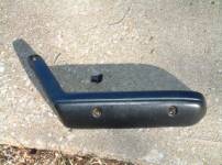
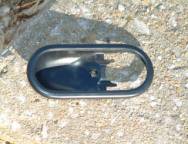
Unscrew the screw holding the inside of the door lock handle and take the inside of the door handle off (as shown in the picture in the middle above). Be gentle, and it will help if you pull the inside handle like you are opening the door.
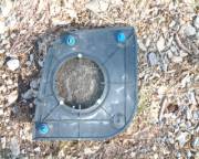
Pop off the speaker cover. It is held on by 4 plastic joints that pop off when you pull. Unscrew the speaker, too.
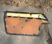
Pull off the inside of the door. Start by pulling on the bottom of the door, unpopping all the joints. Then lift up on the panel, and it should come right off.
Use a knife and cut two slices in the plastic where you will install the actuators. And slice the plastic below the door handle.
Drill the two holes to mount the actuator. Make sure that the rod can go through the hole in the middle of the door. (see picture)
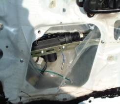
Bend the rod in the loose Z configuration shown. Right now the goal is to make sure that everything is moving freely.
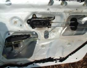
Install the piece that attaches to the power lock rod to the manual lock rod and make sure that everything is moving freely. (See above right picture.)
Do not reassemble door until after you have tested the system.
Wiring Installation:
Install the keyless entry kit and relays under the dash in the vicinity of the steering wheel. You can install it wherever you want, but it may be easiest to install under the steering wheel.
Hook the positive wires to a positive source that is always on. The radio is a good source for this.
Run the Actuator Wiring to the doors. These are the red and black wires in the gray sleeve. Don’t try to get it through the door, yet.
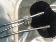
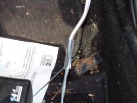
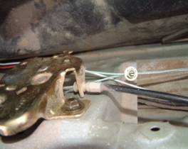
Running the wires to the doors is done in two steps. First of all unsnap the black rubber wire tube from the frame side of the car. There should be wires inside. Undo the white piece also (inside the end of the black tube).
(Shown is the black tube and white insert)
The first step is to get the wires going from inside the car out to the opening by the door. Using the conduit, snake the conduit up and out that opening. This is done starting from underneath the dashboard. You will have to stick your finger in the hole in the frame by the door to guide it. You are using both hands, your left hand on the inside of the car, and your right hand on the outside of the car. Then when you can grab the conduit through the frame opening by the door (with 1 or two fingers), tape the wires to the conduit, and pull the conduit and the wires through the opening.
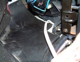
(Pic on left)Note the heater fan (on top) and the dashboard bolt on the right center. The white thing is the conduit being snaked up through the hole on the inside of the car. You start here and using your left hand push the conduit through and feel with your right finger in the opening in the frame by the door.
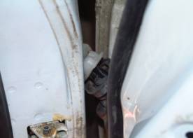
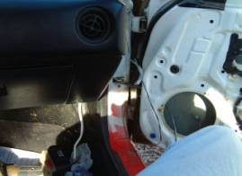
Pic on Right shows the conduit going from inside the car through the frame and out to the space between the car door and the frame. This is your goal.
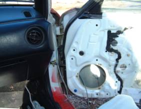
(Left Pic shows taping wires together before you pull them through. Right Pic shows the wires run from the speaker opening through the black tube)
Secondly, starting from inside the door, reaching in from the speaker opening, snake the conduit through the rubber tube and out the top of the rubber tube. Then tape the wires to the conduit and pull the conduit back through. Don’t forget about running the wires through the white piece on the end (car side) of the black tube.
Hook the wires actuator wires up to the actuator, compress them lightly with some pliers, to make sure that they stay attached, and then tape them up, to prevent the metal from contacting other metal and shorting anything out.
Repeat the procedure with the driver’s side. You may have to unbolt the fuse box.
Note: When you are testing the lock/unlock functions, it may be necessary to reverse the lock actuator wires to get lock and unlock to work correctly (instead of backwards).
Power Trunk Instructions:
Position the actuator on the passenger side of the trunk lock.
Unbolt the trunk lock. There should be one rods and one cables connected to it. You will be connecting the power trunk cable by drilling a hole, filing a notch or attaching in another way.
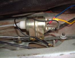
The pictures above illustrate the basic principle. You will need to hook up the positive, negative and lock wires. To run the green actuator wire, unbolt the gas tank filler cover and use the conduit to run the wires to the back of the cabin. Run the wire underneath the seat belt, and under the cover on the bottom of the door opening. Then attach the green wire to the power trunk wire of the keyless entry unit.
Instructions For Push Button On and Off Buttons: The buttons should be wired into the Black wires coming out of the relays. Find a suitable place to mount the buttons, drill holes and install. The other wire coming out of the buttons is wired into ground (-).
Wiring Diagram for Keyless Entry Kit:
![]() +12V
+12V
Red
![]()
Red White
Keyless Entry
Relays
Yellow
![]() Blue/Black Black Optional
Lock/Unlock
Blue/Black Black Optional
Lock/Unlock
Buttons
![]()
![]()
![]()
![]()
![]()
![]()
![]()
![]()
![]() Green / Black Black Join Buttons to Black – Blue/Black
Green / Black Black Join Buttons to Black – Blue/Black
And Black - Blue/Black Wires
![]()
![]()
![]()
Black Red
![]()
![]()
![]()
![]()
![]()
![]()
![]() Violet/Black Red
Violet/Black Red
![]()
![]()
![]()
![]()
![]()
![]()
![]()
To Neg
(-) Blue
White/Red Blue
![]() (to Power Trunk)
(to Power Trunk)
![]()
Lock Motor
![]()
![]() Green Red
Green Red
![]()
Blue Black
Power Trunk Relay![]()
![]()
![]() Green
Green
![]()
![]() Red ( +12v)
Red ( +12v)
![]()
![]()
![]()
![]()
![]() Black Yellow
Black Yellow
![]()
![]() White
White
Blue
Black (to Neg)