Power
Lock and Keyless Entry Installation instructions: Jeep Wrangler
Door Lock Actuator Installation:
Remove the door panels. They are held on by screws and joints that will pop out. You will have to unscrew the inside door handle.
Start by unscrewing all the screws. Then lift up on the panel, and it should come right off.
Remove the plastic on the inside of the door. By careful, because you will be reusing the plastic.
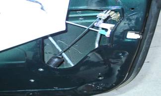
Drill the two holes to mount the actuator. The position of the actuator is shown above in the middle picture. It is mounted diagonally, and the rod goes on the inside of the door.
Do not reassemble door until after you have tested the system.
Wiring Installation:
Install the keyless entry kit and relays under the dash in the vicinity of the steering wheel. You can install it wherever you want, but it may be easiest to install under the steering wheel.
Hook the positive wires to a positive source that is always on. The radio is a good source for this.
Run the Actuator Wiring to the doors. These are the red and black wires in the gray sleeve. Don’t try to get it through the door, yet.
Running the wires to the doors is done by attaching the wires to the black strap that holds the door.
Hook the wires actuator wires up to the actuator, compress them lightly with some pliers, to make sure that they stay attached, and then tape them up, to prevent the metal from contacting other metal and shorting anything out.
Repeat the procedure with the driver’s side.
Note: When you are testing the lock/unlock functions, it may be necessary to reverse the lock actuator wires to get lock and unlock to work correctly (instead of backwards).
Instructions For Push Button On and Off Buttons: The buttons should be wired into the Black wires coming out of the relays. Find a suitable place to mount the buttons, drill holes and install. The other wire coming out of the buttons is wired into ground (-).
Power Tailgate Instructions:
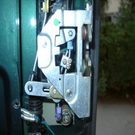
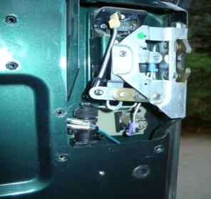
Mount the Actuator:
Note that the linkage rod installed had to be bent in two 90 degree angles and one about 45 degree angle to make it clear the latch assembly, and about half of the length was cut off. I did not secure the rear lock motor on the top with any screws, the linkage being shaped as it is holds the motor vertical and won't allow it to move side to side when it is actuated. However it would have been easy to use one of the straps supplied and secure the motor at the top too.
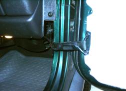
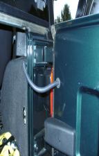
The right picture shows a
3/8" flexible wire tubing (about $3 at Autozone) that is installed into an
existing rubber grommet and tucked behind the carpet. The wiring
continues down the right side of the body, across
the carpet, and up the left side of the door area where it is taped it onto an
existing factory wiring harness that goes all the way down the left side of the
body to the dash.
Wiring Diagram for Keyless Entry Kit:
![]() +12V
+12V
Red
![]()
Red White
Keyless Entry
Relays
Yellow
![]() Blue/Black Black Optional
Lock/Unlock
Blue/Black Black Optional
Lock/Unlock
Buttons
![]()
![]()
![]()
![]()
![]()
![]()
![]()
![]()
![]() Green / Black Black Join Buttons to Black – Blue/Black
Green / Black Black Join Buttons to Black – Blue/Black
And Black - Blue/Black Wires
![]()
![]()
![]()
Black Red
![]()
![]()
![]()
![]()
![]()
![]()
![]() Violet/Black Red
Violet/Black Red
![]()
![]()
![]()
![]()
![]()
![]()
![]()
To Neg
(-) Blue
White/Red Blue
![]() (to Power Trunk)
(to Power Trunk)
![]()
Lock Motor
![]()
![]() Green Red
Green Red
![]()
Blue Black
Power Trunk Relay![]()
![]()
![]() Green
Green
![]()
![]() Red ( +12v)
Red ( +12v)

![]()
![]()
![]()
![]()
![]() Black Yellow
Black Yellow
![]()
![]() White
White
Blue
Black (to Neg)