Power
Lock and Keyless Entry Installation instructions: Jeep
Door Lock Actuator Installation:
Remove the door panels. They are held on by screws and joints that will pop out. You will have to unscrew the door inside door handle.
Start by unscrewing all the screws. Then lift up on the panel, and it should come right off.
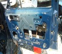
Remove the plastic on the inside of the door. By careful, because you will be reusing the plastic.
Drill the two holes to mount the actuator. The position of the actuator is shown above in the middle picture. It is mounted vertically, and the rod goes on the inside of the door.
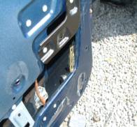
On the Jeep’s without factory power locks, if you follow the door lock/unlock rod down to the actual door lock you will find that it is attached to a lever. You can either install the power lock rod to this lever, or you can attach the rod to the door lock rod. (See above right picture.) The top half of the inside of the doors isn’t very open, so it is probably easier to attach the rod to the lever.
Do not reassemble door until after you have tested the system.
Wiring Installation:
Install the keyless entry kit and relays under the dash in the vicinity of the steering wheel. You can install it wherever you want, but it may be easiest to install under the steering wheel.
Hook the positive wires to a positive source that is always on. The radio is a good source for this.
Run the Actuator Wiring to the doors. These are the red and black wires in the gray sleeve. Don’t try to get it through the door, yet.
On the Jeep that I worked on, there weren’t any wires going to the door. If your Jeep is like this, then you will have to drill holes in the frame and the door to run your wires. If your Jeep has wires running to the doors, then the below instructions apply.
Running the wires to the doors is done in two steps. First of all unsnap the black rubber wire tube from the frame side of the car. There should be wires inside.
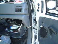
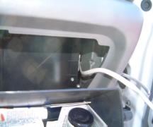
The first step is to get the wires going from inside the car out to the opening by the door. The above right picture shows the inside view of the hole you are aiming for. Remove the glove compartment. This should unscrew, and then you will carefully remove it.
Using the conduit, snake the conduit up and out the opening by the door. This is done starting from underneath the dashboard. Then when you can grab the conduit through the frame opening by the door, tape the wires to the conduit, and pull the conduit and the wires through the opening.
Starting from inside the door, snake the conduit through the rubber tube and out the top of the rubber tube. Then tape the wires to the conduit and pull the conduit back through.
Hook the wires actuator wires up to the actuator, compress them lightly with some pliers, to make sure that they stay attached, and then tape them up, to prevent the metal from contacting other metal and shorting anything out.
Repeat the procedure with the driver’s side.
Note: When you are testing the lock/unlock functions, it may be necessary to reverse the lock actuator wires to get lock and unlock to work correctly (instead of backwards).
Instructions For Push Button On and Off Buttons: The buttons should be wired into the Black wires coming out of the relays. Find a suitable place to mount the buttons, drill holes and install. The other wire coming out of the buttons is wired into ground (-).
Wiring Diagram for Keyless Entry Kit:
![]() +12V
+12V
Red
![]()
Red White
Keyless Entry
Relays
Yellow
![]() Blue/Black Black Optional Lock/Unlock
Blue/Black Black Optional Lock/Unlock
Buttons
![]()
![]()
![]()
![]()
![]()
![]()
![]()
![]()
![]() Green / Black Black Join Buttons to Black – Blue/Black
Green / Black Black Join Buttons to Black – Blue/Black
And Black - Blue/Black Wires
![]()
![]()
![]()
Black Red
![]()
![]()
![]()
![]()
![]()
![]()
![]() Violet/Black Red
Violet/Black Red
![]()
![]()
![]()
![]()
![]()
![]()
![]()
To Neg
(-) Blue
White/Red Blue
![]() (to Power Trunk)
(to Power Trunk)
![]()
Lock Motor
![]()
![]() Green Red
Green Red
![]()
Blue Black
Power Trunk Relay![]()
![]()
![]() Green
Green
![]()
![]() Red ( +12v)
Red ( +12v)
![]()
![]()
![]()
![]()
![]() Black Yellow
Black Yellow
![]()
![]() White
White
Blue
Black (to Neg)